ERROR Checking in Computer Networks | CBSE Class 12
ERROR Checking in Computer Networks is useful to to avoid errors while transmitting data from sender to receiver. To avoid errors in transmission, some error detection or error checking methods are used in computer networks that ensure if the received packet is error free or not. Here in this section, we are going to talk about some common error checking methods in networks.
While transmitting data over networks, some errors may occur, and data may get corrupted, for example, if the sender is trying to send a data in binary form as 10110111 and the data received by the receiver as 10110101. If you look carefully, a bit (the 2nd bit from the right) has changed. This means that intended data has not reached the receiver node and hence it is an error.
The errors can be one or more of following types:
- Single-bit error. If only one bit of the transmitted data got changed from 1 to 0 or from 0 to 1.
- Multiple-bit error. If two or more nonconsecutive bits in data got changed from 0 to 1 or from 1 to
- Burst Error. If two or more consecutive bits in data got changed from 0 to 1 or from 1 to 0.
ERROR Checking in Computer Networks
In this section “ERROR Checking in Computer Networks“, we will provide a comprehensive introduction to all types of errors that may occurs in Computer Networks with examples including the following topics
- Single Dimensional Parity Checking.
- Advantages of Single Dimensional Parity Checking
- Drawbacks of Single Dimensional Parity Checking
- Two – Dimensional Parity Checking
- Advantages of Two-Dimensional Parity Checking Technique
- Drawbacks of Two-Dimensional Parity Checking Techniqu
And, by the end of this tutorial, you will have a solid understanding of all about ERROR Checking in Computer Networks and will be able to use this knowledge in their own network projects.
Also this tutorial covers all necessary topics/concepts required to complete your exams preparations in CBSE schools / classes 11th and 12th.
Also , you can Sign Up our free Computer Science Courses for classes 11th and 12th.

————————————————————————————————————————–
Single Dimensional Parity Checking
Parity refers to an additional bit added to the actual data. Single dimensional parity check works as described below.
(For understanding purposes, we are using two sample data units as 10110111 and 11001011.)
Before transmission, at the sender node
Number of 1’s is counted in the actual data unit.
- In 10110111, the number of 1’s is 6, which is an even number.
- In 11001011, the number of 1’s is 5, which is an odd number.
Add an extra bit (either 0 or 1), called the parity bit to actual data so that the number of 1’s along with the extra bit, become even or remain even, i.e., for odd number of 1’s, add 1 as the parity bit and for even number of 1’s, add 0 as the parity bit.
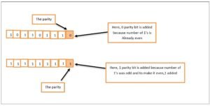
The data is now transmitted along with the parity bit.
After transmission, at the receiver node
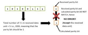
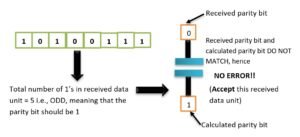
From the received data, excluding the parity bit, once again determine the parity bit using the same process, i.e., by calculating the number of 1’s in received data and compare it with the received parity bit. If the received parity bit matches with the calculated parity bit, data is considered as CORRECT, otherwise the received data unit is considered as CORRUPTED data and hence rejected. Say, the received data is like 10100111 and 11001011.
- From the received data unit 10100111, recalculating the parity bit from the data unit part only (excluding the received parity):
- Similarly, for other received data unit, i.e., 11001011, recalculating the parity bit from the data unit part only (excluding the received parity bit):
Since this parity check is based on making the number of bits as even, it is EVEN PARITY checking. There is ODD parity technique also, very similar to this. – the only difference is that parity is calculated to make the number of bits ODD.
For Parity Checking technique, the sender and receiver nodes already agree upon which technique (EVEN or ODD parity) will be used for error checking.
Advantages of Single Dimensional Parity Checking
The single dimensional parity checking technique offers following advantages:
It is a simple mechanism, which is easy to implements.
It is an inexpensive technique for detecting the errors in data transmission.
Drawbacks of Single Dimensional Parity Checking
The single dimensional parity checking technique suffers from following drawbacks :
It can detect only single-bit errors which occur rarely.
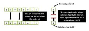
If, in the data transmitted, two bits get interchanged, then even though data affected, but the parity bit will remain correct. In such cases, this technique cannot detect the errors, e.g,.
Two – Dimensional Parity Checking
This is an enhanced version of single dimensional parity checking technique, This technique works with multiple data units simultaneously. This technique works as described below:
(For understanding purposes, data units being sent are : 11010001, 00100000, 00111100, 10010001)
At the sender node, before transmission
- Organize all data units being sent, one below another so that it appears as table of bits, i.e.,
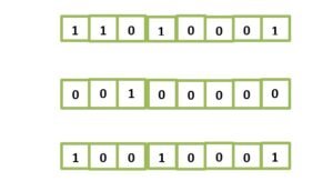
- Calculate parity bits for each data unit row-wise and column-wise. Consider one data unit as a row and bits below one another as columns. Thus, in above data we can say there are four rows and eight columns of bits. That is, calculate column parity as depicted below and row parity in the same manner as you did in single-dimensional parity check.
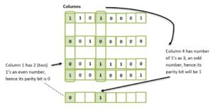
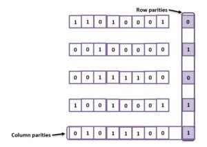
In the same manner, calculate the parity bits for all columns, and also for rows, i.e., two-dimensional parities. So the set of data units along with row parities and column parities will be like as shown here.
The data units are now transmitted with the row parity bits and column parity bits.
At the receiver end, after transmission
The row parity bits and column parity bits are again recalculated using the received data parts only (excluding the parity bits) and compared with the received row parities and column parities. If these match, data is accepted, otherwise rejected, as this indicates ERROR in transmission.
Say received data units are :
11001001 (Notice two bits got swapped here),
00100000, 00111100, 10010001 (Notice there is error only in first data unit).
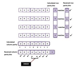
As you can notice that with row parity bits only, errors cannot be detected. However, with two-dimensional parity bits (row parity and column parity), errors can be detected.
Advantages of Two-Dimensional Parity Checking Technique
The two-dimensional parity checking technique offers these advantages:
- It is more efficient than single dimensional parity technique.
- It can detect multiple bit errors also, which sometimes single dimensional parity checking technique cannot.
Drawbacks of Two-Dimensional Parity Checking Technique
The two-dimensional parity checking technique suffers from following drawbacks:
- It cannot detect compensating multiple bit errors. That means, if two bits in One data unit get corrupted and the two bits at the exact same position in another data unit also get corrupted so that they do not affect row-and column parities, then such an error will go undetected. For example, consider the same example data units as above. If the received data units are as 11001001, 00100000, 00111100, 10001001 – the two bits in first and last data units at exact same positions got corrupted.
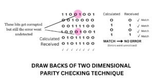
- This technique cannot detect 4-or more-bit errors in some cases.
Checksum
The term checksum refers to a sum of some bits calculated from digital data that is used to ensure the data integrity at the receiver’s end. The checksum is calculated as per a specific scheme and is used for error checking in computer networks. The checksum error detection scheme works as described below:
At the sender node, before transmission
- The data being transmitted is divided into equal sized k number of segments, where each segment contains m number of bits.
- The divided k segments are added using 1’s complement arithmetic and extra bits (more than m bits) are added back to the sum (wrap-around).
- The final sum’s complement is calculated. This is the checksum.
- Now all the data segments (k segments having m bits each) is sent along with the checksum.
At the receiver node, after transmission
- Step (ii) is repeated at the receiver end, i.e., all the data segments are added using 1’s complement arithmetic (with extra bits wrapped around) to get the new sum.
- This calculated new sum is added with the received checksum and then complemented. Now,
- if the result is all O’s, the transmission is successful (i.e., NO ERROR) – ACCEPT the data.
- if the result is not all 0’s the transmission is ERRONEOUS- REJECT the data.
In order to calculate checksum practically with some data units, following binary addition rules are used,
- 0 + 0 = 0, 0 +1 = 1,1 + 0 = 1,
1 + 1 + 11 (where left 1 is a carry bit)
b . Add the last carry bit to the result (wrap-around),e.g.,
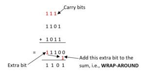
Now let’s see how checksum error detection technique works with some data units.
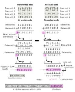
Please note that there are many other error checking techniques like CRC (Cyclic Redundancy Check),


