
Boolean Logic | CBSE Class 11 | Computer Science
Dear Class 11th STUDENTS,
Welcome to this tutorial of Boolean Logic from your CBSE class 11 of Computer Science Syllabus .
In this tutorial, we shall be learning our chapter-4 from Unit 1: Computer Systems and Organisation (CSO) as CBSE BOARD suggested to learn about computer system and its organisation to complete this section.
Unit 1: Computer Systems and Organisation (CSO)
Chapter 4: Boolean Logic
- Logic gates: NOT, AND, OR, NAND, NOR, XOR
- Truth tables
- De Morgan’s laws
- Logic circuits
I advice you to check the latest syllabus given by CBSE Board at its Official website: www.cbseacademic.nic.in
Also, in this tutorial we will covers all necessary topics/concepts required to complete your exams preparations in CBSE classes 11th.

NOTE:
- We are also giving some important Questions & Answers for better understanding as well as preparation for your examinations.
- You may also download PDF file of this tutorial from our SHOP for free.
- For your ease and more understanding, we are also giving the video explanation class of each and every topic individually, so that you may clear your topics and get success in your examinations.

Introduction to Boolean Logic
Long ago Aristotle constructed a complete system of formal logic and wrote six famous works on the subject, contributing greatly to the organization of man’s reasoning. For centuries afterward, mathematicians kept on trying to solve these logical problems using conventional algebra but only George Boole could manipulate these symbols successfully to arrive at a solution with his own mathematical system of logic. Boole’s revolutionary paper ‘An investigation of the laws of the thought’ was published in 1854 which led to the development of new system, the algebra of logic, ‘BOOLEAN ALGEBRA’ or ‘BOOLEAN LOGIC’.
Boole’s work remained confined to papers only until 1938 when Claude E. Shannon wrote a paper titled ‘A Symbolic Analysis of Relay Switching Circuits’. In this paper he applied Boolean Logic to solve relay logic problems. As logic problems are binary decisions and Boolean logic effectively deals with these binary values. Thus, it is also called ‘Switching Algebra’.
Every day we have to make logic decisions: “Should I carry the book or not?’’ “Should I use calculator or not?’’; “Should I miss TV Program or not?’’. Each of these questions requires a YES or NO answer as there are only these two possible answers.
Therefore, each of the above mentioned is a binary decision. Binary decision making a also applies to formal logic.
For example, let us consider the following:
- Indira Gandhi was the only woman Prime Minister of India.
- 13- 2 = 11.
- Delhi is the biggest state in India.
- What do you say?
- What did I tell you yesterday?
1st and 2nd sentences which can be determined to be true or false are called logical statements or truth functions and the results TRUE or FALSE are called truth values. The truth values are depicted by logical constants TRUE and FALSE or 1 and 0. 1 means TRUE and 0 means FALSE. And the variables which can store these truth values are called logical variables or binary valued variables as these can store one of the two values TRUE or FALSE.
Basic Logic Gates
After Shannon applied Boolean logic in telephone switching circuits, engineers realized that Boolean algebra could be applied to computer electronics as well.
In the computers, these Boolean operations are performed by logic gates.
Now let’s see What is a logic gate?
A Gates is a basic electronic circuit which operators on one or more signals to produce an output signal
Gates are digital (two – state) circuits because the input and output signals are either low voltage (denotes 0) or high voltage (denotes 1). Gates are often called logic circuits because they can be analyzed with Boolean logic. There are three types of logic gates:
- Inverter (NOT gate)
- OR gate
- AND gate
Logical NOT Gate (Inverter)
An inverter (NOT Gate) is a gate with only one input signal and one output signal; the output state is always the opposite of the input state.
An inverter is also called a NOT gate because the output is not the same as the input. The output is sometimes called the complement (opposite) of the input.
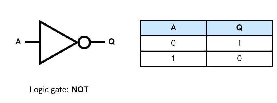
Following tables summaries the operation:
Table truth table for NOT gate
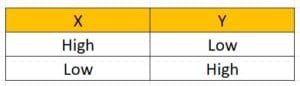
Alternative truth Table for NOT Gate
A low input 0 produces high output 1, and vice versa. The symbol for inverter is given below.
Logical AND gate
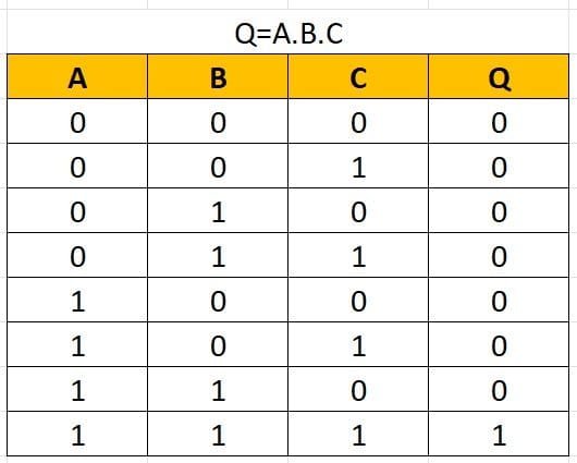
The AND Gate can have two or more than two input signals and produce an output signal. When all the inputs are 1 i.e., high then the output is 1 otherwise output is 0 only.
If any of the inputs is 0, the output is 0. To obtain output as 1, all inputs must be 1.

Where Q=A.B
An AND gate can have as many inputs (2 or more inputs) as desired. Following tables illustrate AND action
Logical OR Gate
The OR Gate has two or more input signals but only one output signal. If any of the input signals is 1 (high), the output signal is 1 (high).
If all inputs are 0 then output is also 0. If one or more inputs are 1, the output is 1.
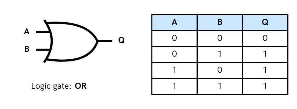
An OR gate can have as many inputs (2 or more inputs) as desired. No matter how many inputs are there, the action of OR gate is the same: one or more 1 (high) inputs produce output as 1.
Following tables show OR action
More about Logic Gates
We have covered three basic logic gates NOT, OR, AND so far. But there are some more logic gates also which are derived from three basic gates (i.e., AND, OR and NOT). These gates are more popular than NOT, OR and AND and are widely used in industry. This section introduces NOR, NAND, XOR, XNOR gates.
Logical NOR Gate
The Nor Gate has two or more input signals but only one output signal. If all the inputs are 0 (i.e., low), then the output signal is 1 (high).
If either of the two inputs is 1 (high), the output will be (low). NOR gate is nothing but inverted OR gate.
Following truth Tables illustrate NOR action.
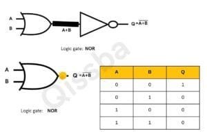
The NOR gate can have as many inputs (2 or more inputs) as desired. No matter how many inputs are there, the action of NOR gate is the same i.e., All 0 (low)inputs produce output as 1.
Logical NAND Gate
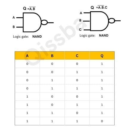
The NAND Gate has two or more input signals but only one output signal. If all of the inputs are 1 (high), then the output produced is 0 (low).
NAND gate is inverted AND gate. Thus, for all 1(high) inputs, it produces 0 (law)output, otherwise for any other input combination, it produces a 1 (high) output. NAND gate can also have as many inputs as desired.
NAND action is illustrated in following Truth Table.
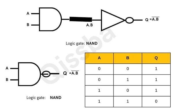
The NAND gate can also have as many inputs (2 or more inputs) as desired. No matter how many inputs are there, the action of NOR gate is the same i.e., All 0 (low)inputs produce output as 1.
Logical XOR Gate (Exclusive OR Gate)
The XOR Gate can also have two or more inputs but produces one output signal. Exclusive-OR gate is different from OR gate. OR gate produces output 1 for any input combination having one or more 1’s, but XOR gate produces output 1 for only those input combinations that have odd number of 1’s.
Following figure with Truth Table illustrate XOR operation.
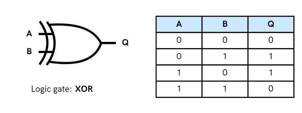
In boolean algebra “⊕” sign stands for XOR operation. Thus, A XOR B can be written as A ⊕ B.
XOR addition can be summarized as follows:
0 + 0 = 0, 0 + 1 = 1, 1 + 0 = 1, 1 + 1 = 0
Logical XNOR Gate (Exclusive NOR Gate)
The XNOR Gate is logically equivalent to an inverted XOR i.e., XOR gate followed by a NOT gate (inventor). Thus XNOR produces 1 (high) output when the input combination has even number of 1’s. Following tables (3.35 and 3.36) illustrate XNOR action.


The bubble (small circle), on the outputs of NAND, NOR, XNOR gates represents complementation.
Truth Tables
A truth table for a logic gate displays the output of the gate for all possible combinations of its inputs. In the context of CBSE Class 11th, you’ll encounter truth tables for basic logic gates like AND, OR, NOT, and their variations.
A truth table is a mathematical table used in logic, particularly in Boolean algebra, to demonstrate the output of a logical expression for all possible input combinations. It shows the relationship between input values and the resulting output of a logic gate or circuit.
Truth tables are used to represent and analyze Boolean expressions, which are expressions that can be evaluated as either true or false.
Truth tables are fundamental for understanding the behavior of logic gates and designing digital circuits. They provide a clear and concise way to visualize and analyze the relationship between inputs and outputs.
Examples of Truth Tables:
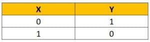
NOT Gate (Inverter) : Truth Table
AND gate Truth Table
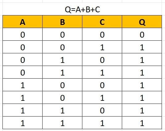
OR Gate Truth Table
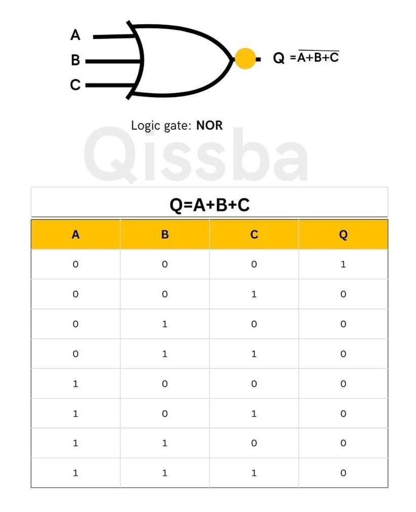
NOR Gate Truth Table
NAND Gate Truth Table
XOR Gate (Exclusive OR Gate) Truth Table
XNOR Gate (Exclusive NOR Gate) Truth Table
Logic Circuits
A logic circuit is a circuit that carries out a set of logic actions based on an expression. To execute a Boolean expression, you require a logic circuit and the input values for the variables of Boolean expression.
You can represent a Boolean expression in the form of a logic circuit using a logic gates so that the output of the Boolean expression can be determined for various combinations of input values. Logic circuit diagrams are used to represent Boolean expressions through the combination of logic gates.
The rules to create a logic circuit are:
1.Break the Boolean expression in smaller sub expressions, example.
for a Boolean expression: AB+ BCD, there are two sub-expressions: AB and BCD.
2.For each sub-expression, determine the logic gates that can implement them. (Refer to Example 3.5 to recall this), e.g.
for sub-expressions determined in previous step,
AB : requires AND gate
BCD: requires NOT and AND gates
3. Implement the sub-expressions using the gates determined in previous steps:

- Determine the Logic gate for the symbol joining the sub-expressions, e.g
for the given expression,
symbol + joins the sub-expressions (AB and BCD); the symbol + signifies OR gate.
- Using the logic gate for the joining symbol (from step 4), connect the sub-expressions gate implementation (from step 3)
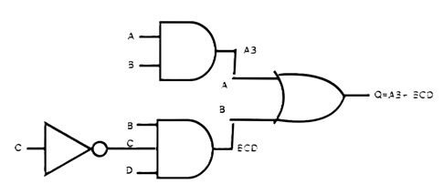
- Now! Our logic circuit diagram is ready.
De-Morgan’s Theorems
We use De Morgan’s theorems to solve the expressions of Boolean Algebra. One of the most powerful identities used in Boolean logic and digital design is De-Morgan’s theorem. Augustus De Morgan had paved the way to Boolean logic by discovering these two important theorems. This section introduces these two theorems of De-Morgan. This theorem explains that the complements of the products of all the terms are equal to the sums of the complements of each and every term. Likewise, the complements of the sums of all the terms are equal to the products of the complements of each and every term.
In this tutorial, we will have a look at De Morgan’s Theorems according to CBSE Class 11th syllabus.
What are De Morgan’s Theorems?
Two of the theorems were suggested by De Morgan that are extremely useful for Boolean Algebra. These two theorems are going to discussed below in this tutorial.
De-Morgan’s First Theorem
It state that:
![]()
Where NAND= Bubbled OR
The LHS (left-hand side) of this theorem represents the NAND gate that has inputs A and B. On the other hand, the RHS (right-hand side) of this theorem represents the OR gate that has inverted inputs. The OR gate here is known as a Bubbled OR.

Here is a table that shows the verification of the first theorem of De Morgan:
De-Morgan ‘s Second Theorem
This theorem states that:
![]()
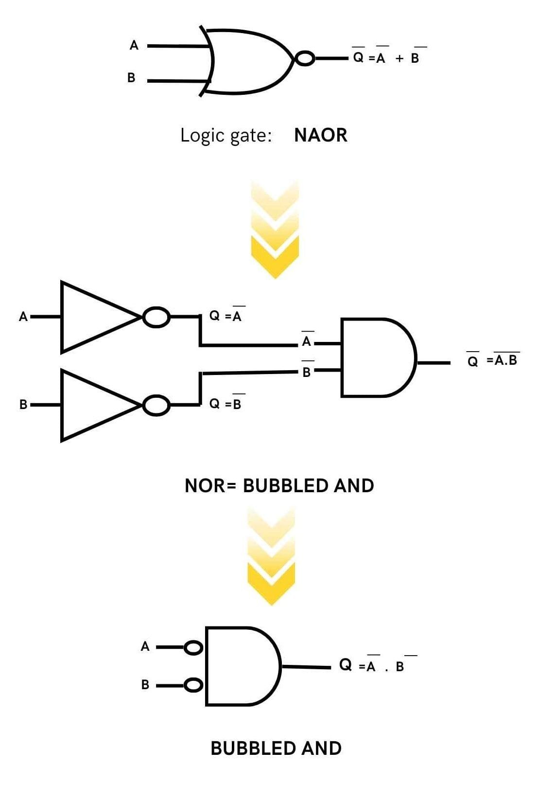
NOR=Bubbled AND
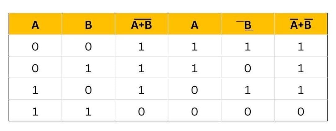
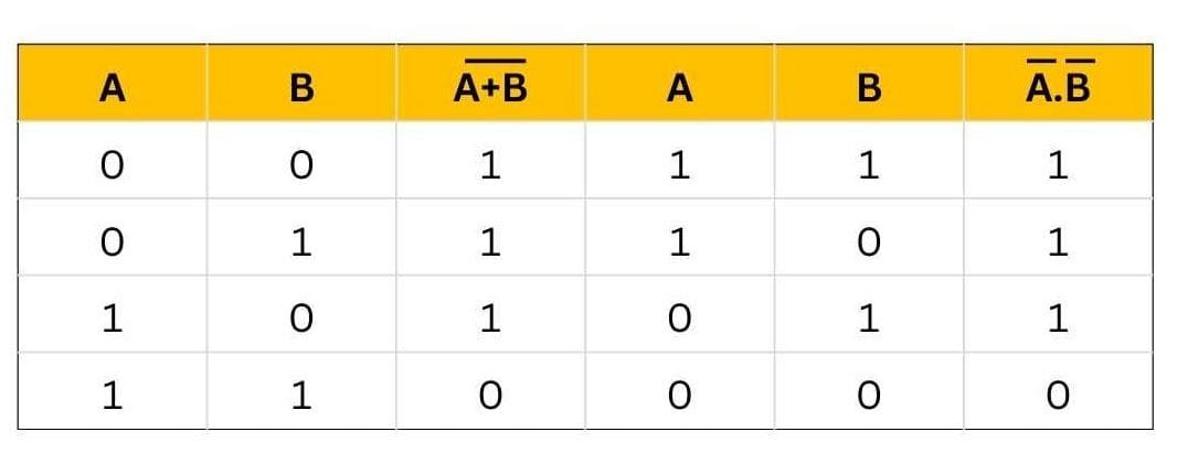
The left-hand side of this theorem represents the NOR gate that has inputs A and B. On the other hand, the right-hand side represents the AND gate that has inverted inputs. The AND gate here is known as a Bubbled AND.
Here is a table that shows the verification of the second theorem of De Morgan:
You may also like
Malwares: Viruses, Trojans, and Adware | CBSE Class 11

Cyber Crime | CBSE Class 11 | Computer Science